


_0001.jpg)


.jpg)


.jpg)


.jpg)


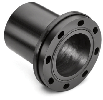 VP flange with fibre-reinforced plastic backing flange.
For thousands of years, pipelines have been used for the defined supply or discharge of fluids. In each era, the choice of material was determined by availability and the latest technology: right from underground masonry sewerage systems that date back to 3,800 BC to the wooden water pipes and cast iron pipes that emerged in the Middle Ages.
Cast iron pipes were standardised as early as 1873, and standard flange sizes were established as the “dimensional standards of 1882” shortly afterwards by the Association of German Gas and Water Specialists in cooperation with the Association of German Engineers.
In 1926, it was established that the screw holes on flanges must be arranged symmetrically to both main axes irrespective of the material used, and their number must always be divisible by four1. This remains valid today and is currently determined in Europe by EN 10922.
 |
|
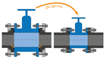
Figure 5: Smaller valve through use of special flange or VP flange. |
In the 1930s, the raw materials used until then, that is, cast iron, steel, stoneware etc, were supplemented on the market by the first artificially produced materials – rigid PVC (unplasticised polyvinyl chloride) and HDPE or LDPE (high-density or low-density polyethylene)3. Analogously to the known pipes, the dimensioning and quality criteria for these innovative pipes were then also gradually set out in standards to emphasise their importance for pipeline construction. For instance, the first standard for pipes made of rigid PVC (today PVC-U) dates from 1941. Polyethylene became of interest for pipe manufacturing in the 1950s and was then standardised for the first time in 1960 with pipe standards DIN 8074/80754 for HDPE and DIN 8072/80735 for LDPE.
Down through the years, HDPE was developed further, with its properties in terms of creep rupture strength significantly improved in several steps, with the result that today HDPE is one of the main materials in the municipal supply and waste management market.
The polyethylene material used can be divided into three types: PE 63 (first generation) with an MRS (minimum required strength) of 6.3 MPa; PE 80 (second generation) with an MRS of 8.0 MPa; and PE 100 (third generation), which is the kind used most widely today, with an MRS of 10.0 MPa. The numeral after the acronym PE is a dimensionless number that is determined according to the creep rupture strength under internal pressure at 20 deg C after 50 years with water as the test medium.
For transitions to another pipe material as well as detachable connections between these pipes, the flange connection was the only option available at that time. Standardised loose flanges that enabled pairing with corresponding counterflanges of the same size, analogously to those used in steel piping systems, were developed. The polyethylene welding stub required for usage with loose flanges was then also developed, for example, according to the standard for steel flanges (Figure 1).
 |
|
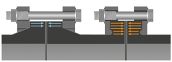
Figure 6: Comparison of welding stub with HP flange surface. |
Flange & pipe dimensioning
Flange connections are used to create tight but detachable joints between pipe sections. The correct contact pressure of the annular sealing surfaces of the flange on the interjacent gasket ensures the tightness of the system.
The flange is usually attached by screws that are inserted through bore holes in the flange faces. A flange connection consists of two flanges, a gasket matching the sealing surface, and a certain number of screws with nuts and washers.
There are two versions of flanges: fixed and loose. Fixed flanges are either included in the casting during the manufacture of cast iron pipes (flanged pipes: F pieces or FF pieces) or can be welded to the front end of the pipe as separate fittings.
The loose flange lies loosely on the pipe and requires an additional component, the stub end or welding neck, so that a flange connection can be created. Unlike the fixed flange, it can be positioned in line with the hole pattern on the counterflange for assembly.
In designing a pipe system, factors such as pressure, temperature, medium and mass flow must be taken into account, with the mass flow and the maximum acceptable pressure loss basically determining the required pipe cross-section.
Since a pipe could not be manufactured for every calculated internal pipe diameter, nominal pipe sizes were set out in the standards. Based on these nominal pipe diameters, both the pipes and flanges were then designed according to pressure levels that were also pre-defined. This means that the connecting dimension of a flange can be clearly determined according to the nominal pipe size DN and pressure level PN.
In Germany, DIN EN 1092 sets out dimensions and designs for flanges of nominal pipe sizes DN 25 to NPS 4,000 and for pressure levels PN 2.5 to PN 400 with respect to the largest outside diameter D, the pitch circle diameter K, and the number of screw holes and their diameters.
DN (Diameter Nominal) and PN (Pressure Nominal), followed by a dimensionless number, are alphanumerical parameters of a piping system component that are used for reference purposes. They are indirectly related to the physical size of the bore hole or to the outside diameter of the connections in mm or to the maximum permissible pressure in bar, with respect to a combination of mechanical and dimensional characteristics of a component.
The manufacture of HDPE pipes according to standard DIN 8074/8075, for instance, generally takes place using the vacuum extrusion process. Here, the plastic mass of the HDPE produced in the annular extrusion process is shaped by means of vacuum calibration to obtain the outside diameter.
The desired wall thickness of the pipe is obtained via a precisely coordinated interplay between material addition and haul-off speed. The outside diameters set out in this standard follow certain preferred numbers, known as the Renard series according to ISO 36 or ISO 40657 or DIN 3238.
In this way, the appropriate wall thicknesses of the pipes can be determined by defining the pipe series S, which stands for a certain outside diameter/wall thickness ratio (SDR = standard dimension ratio) in each case.
Taking into account the respective material properties and a total operating (calculation) coefficient (safety factor), the pipe is then assigned a pressure class.
In conformity with the standard, the designation of a HDPE pipe must contain information on the material used (strength value) and the corresponding standard as well as the outside diameter and the pipe series S or the SDR. Thus, the internal diameter or the actual nominal pipe size is defined only indirectly. This must be taken into account when calculating pipe networks and when selecting flanges.
That particular attention must be paid to the designation of the pipes (and fittings) during planning is shown by the naming of HDPE pipes according to DIN EN 12201-29 or DIN EN 1555-210, for example. Herein the nominal outside diameters dn of the pipes are assigned to a nominal pipe size DN/OD. The nominal pipe size DN/OD is a numerical figure for the size of a pipeline part, except those that are characterised by a thread. It corresponds approximately to the manufacturing size in mm and is related to the outside diameter. For example, the nominal outside diameter dn 250 mm corresponds to the nominal pipe size DN/OD 250 with a calculated internal diameter or the nominal pipe size 204.6 mm in the version according to SDR 11. It is, therefore, important to know which “nominal pipe size” is being discussed.
Plastic pipe-flange connections
As mentioned above, the first flange connections for plastic pipes consisted of accordingly designed loose flanges and weld stubs. This combination is still used extensively today. At the same time, the loose flanges are of varying design and made of materials such as galvanised steel and stainless steel, those with a plastic sheathing (PP-St) and plastic coating, or those consisting entirely of plastic with or without fibre reinforcement.
Each pipe or welding stub dimension can only be paired with a loose flange of a certain dimension (nominal pipe size DN). For example, pipe DN/OD 250 or dn 250 mm with a corresponding welding stub for a pipe dn 250 mm requires a loose flange DN 250. With this flange, a flange transition to a valve or a flange of a steel or cast iron pipe with the nominal pipe size DN 250, for example, could be created. That the hole patterns must be identical in accordance with the pressure level of both flange partners is self-evident.
Figure 4 (Nominal diameter dilemma) shows that the flange dimension DN 250 corresponds but the internal diameters of the two system components are very different and jumps in the internal diameter of the nominal pipe size occur. In addition to this particularity, the PE welding stub was designed in accordance with the steel flange and, due to the mechanical properties of HDPE, displays different behaviour under stresses in the limit range, especially in the case of dimensions from dn 200 mm or DN/OD 200 (flange size DN 200) upwards.
In the case of piping systems under internal pressure in the permissible component operating pressure PFA (pression de fonctionnement admissible, French for allowable operating pressure) range, failures frequently occur in the case of welding stub-loose flange combinations.
The forces generated by the high internal pressure cause deformation of the stub (Figure 2), which results in displacement of the stub and inevitably a reduction in the sealing surface.
The special arrangement of loose flange and welding stub with a correspondingly small contact surface for force transmission favours this effect. Precise information on when a failure of the loose flange-welding stub combination occurs under the above-mentioned conditions cannot be found. Even in the DVS 2210-1 Supplement 311 Part 2.1 Welding Stubs, there is only a note mentioning that the dimensioning of the welding stub allows no conclusions to be drawn as to its strength or the strength of the flange connection.
This “nominal pipe size dilemma” was constructively tackled many years ago by Karl-Albert Reinert, the founder of Reinert KG (later Reinert-Ritz), and resolved specifically for plastics.
The result was the so-called special flange, a drilled-through PE stub with a steel backing flange (Figure 3).
Europlast in Oberhausen, a pioneer plastic pipe manufacturer, listed a special flange of this type in its technical catalogue for the first time in 1980.
Special flanges are still widely used today. The particularity here is that the same flange size as that of the corresponding loose flange is not used for this pipe dimension, with the result that only a fixed flange would result from the loose flange connection, but the nominal pipe size is one step smaller.
The hole circle K is thus closer to the outer pipe diameter. To distribute the bolting forces over the rear side of the stub and therefore ensure the strength of the flange solution, a special steel flange with the same hole pattern is used. This solution also prevents the other deficiency of the loose flange-welding stub combination, namely the buckling of the stub.
This means that not only a pressure class-compatible flange connection but also the connection of PE pipe to cast iron or steel valves and flange pipes of the same nominal size (related to the internal diameter) is possible and this enables the use of smaller valves.
For example, a valve DN 200 can be connected to a pipe DN/OD 250 or dn 250 mm SDR 11 with an internal diameter (nominal pipe size) 204.6 mm using a special flange DN 200/d 250 SDR 11. Here, the choice of a loose flange-welding stub combination only allows a valve of the dimension DN 250 (Figure 4 and Figure 5).
However, in the event that a pressure-class compatible, permanently tight flange connection is required – for which a special flange solution is not possible dimensionally or the degree of freedom of a loose flange connection is necessary – Reinert Ritz has a plastics-compatible solution in its product range.
Since the end of the 1990s, an HP (high-performance) flange variant has existed that can even be designed for certain applications up to 25 bar and other applications up to DN/OD 2000. The particularity of the plastics-compatible HP flange is that the PE stub and the backing flange are delivered as a single unit and are exactly attuned to one another.
The specially designed backing flange interlocks in a positive fit with the back of the stub over an enlarged contact surface directly at the outer pipe diameter and also supports the stub at the outer diameter (Figure 6).
This counteracts deformation of the PE stub through generally high stress and, with the appropriate gasket, provides for a reliable and tight flange connection. Incidentally, influences of the sealing surface, gasket, screws and the flange in itself apply for all transitions produced with flanges. They are essential elements of the “flange connection” system. The pressure-class compatibility, that is, the high performance of the HP flange solution then also led to the choice of the name.
A new, future-oriented variant of the backing flange for both special flanges and HP flanges from Reinert-Ritz is becoming increasingly popular: this extremely lightweight version is made of fibre-reinforced plastic (HP and VP flanges).
Due to the low weight, handling and further processing – depending on the size – are significantly reduced. Another major advantage is the non-corrosiveness of the flange, which means that it can be used without difficulty even in an aggressive environment.
The combination of plastic flange and further constructional enhancements forms the basis for the VP (valve performance) flange, which has elongated holes in the PE stub that greatly facilitate alignment of the valve or the stub during professional assembly. After installation, the VP flange offers continuous bolt preload, thanks to the design of its backing flange with a disc spring effect (Figure 7). This bolt preload still predominates after the tightness test.
Permanently tight flange transitions in plastic piping systems to valves and flanges of other pressure pipe systems can be implemented safely and reliably with sophisticated solutions from Reinert-Ritz – which provides reliable components for flange challenges.
References
1. E-Book Cast Iron Pipes 05/2014
2. EN 1092 Flanges and their joints
3. W. Müller und E. Ant, The History of Plastic Piping, Plastic Piping Manual, KRV
4. DIN 8074 and DIN 8075 Pipes Made of Polyethylene (PE) – PE 80, PE 100
5. DIN 8072 and DIN 8073 Pipes Made of Polyethylene plasticised (PE) – NB: Document withdrawn
6. ISO 3 Preferred numbers; Series of preferred numbers
7. ISO 4065 Thermoplastics pipes. – Universal wall thickness table
8. DIN 323 Preferred numbers and series of preferred numbers
9. DIN EN 12201 Plastics piping systems for water supply and for drainage and sewerage under pressure - Polyethylene (PE)
10. DIN EN 1555 Plastics piping systems for the supply of gaseous fuels - Polyethylene (PE)
11. DVS Guideline 2210-1 Supplement 3 Industrial pipelines made of thermoplastics. Planning and implementation – Aboveground pipe systems – Flange connections: Description, requirements, assembly.
* Since 1970, Reinert-Ritz has focused on developing high-quality products for pipeline construction that are sold worldwide. Hollow bars and solid rods extruded from polyethylene and polypropylene with diameters of up to 1,200 mm or 2,400 mm are Reinert-Ritz’s core expertise. They form the basis for semi-finished products and fittings for their application in pressure pipeline systems of up to 25 bar nominal pressure deployed in gas, oil and water distribution systems as well as in the chemical industry.
Reinert-Ritz is represented by BMC Gulf in the region and will be participating at the latter’s stand at The Big 5 in Dubai at No 2B69.